
A funny thing happened when people started hearing that I was learning to restore and repair old vintage radios and equipment. Suddenly I started hearing from quite a number of people that they had an old radio they would like me to look at for them. I had not realized that there were so many old tube radios still around, but I have started to realized that actually, quite a lot of people might have one or two, sitting deep in storage somewhere.
I thought a bit about why this might be and the conclusion I came to is that a lot of people probably inherited a radio from a grandparent perhaps, or other relative who passed away. The radio has sentimental value as a result, so they don't want to get rid of it certainly, but they also don't really know what to do with it. Probably, they have tried turning it on and it doesn't work. But sadly, gone are the days of a radio or TV repairman downtown who you could just take it to and have it repaired. So unless they happen to hear about a local person who can do the job, the radio just sits in storage, waiting for its day.
This is great for me, because to me, I love the process of the restoration. I love the challenge of figuring out what is wrong with it, what needs fixed, and I love hearing it come to life for the first time in who knows how many years.
A piece of advice however, to anyone reading who may have an old tube radio like this that you would like to have restored someday, while I know its tempting to just try turning it on and see if it works, it's best to resist that urge. Most any radio old enough to have tubes in it probably also had the older style paper and wax capacitors and by now, they have almost certainly gone bad, or likely will when jolted with 120v suddenly after decades of silence. If the capacitors fail, they can often damage other more expensive components, resulting in more work and more parts needed for a restoration. Additionally, many of these old radios were not wired very safely, and can pose a shock hazard if not properly handled.
Acquisition
This radio is an example of one that was inherited from a relative, didn't work, but was kept anyway for sentimental reasons. However, this particular radio fortunately did not wind up in storage collecting dust. In fact, I probably saw it numerous times without even realizing it.
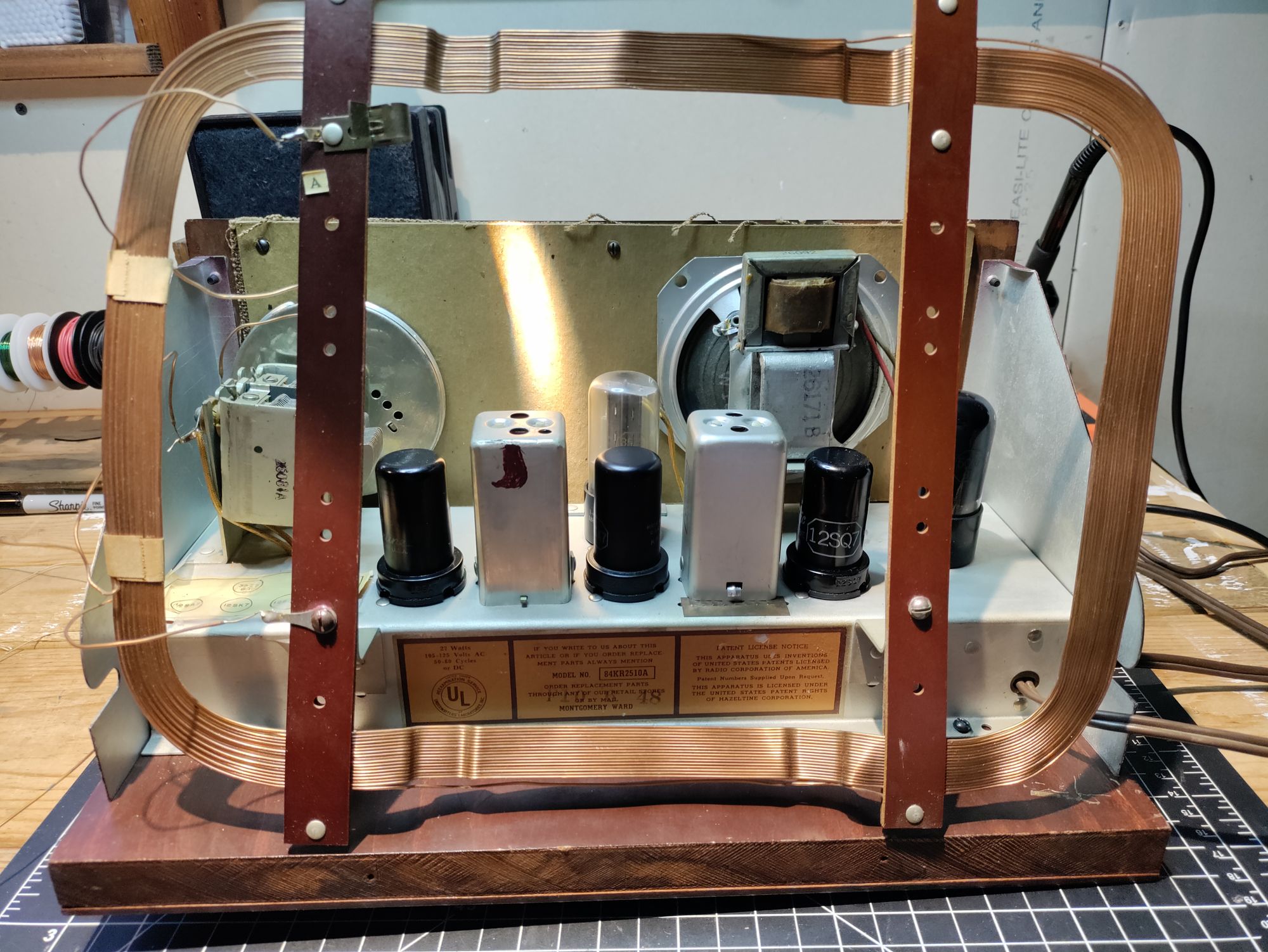
My wife's step-grandfather approached me about restoring this old Airline 84KR-2510A receiver. This is a very unique radio I was not previously familiar with. It is built into a small end table. The table sat in the basement for years after the owner, Mike, had refinished the table and cabinet it was housed in. I had been in that basement many times, and had no idea that it housed a radio.
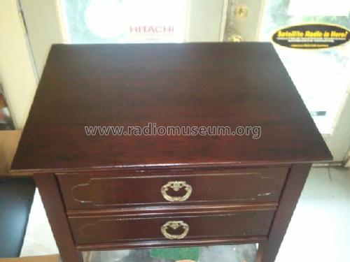
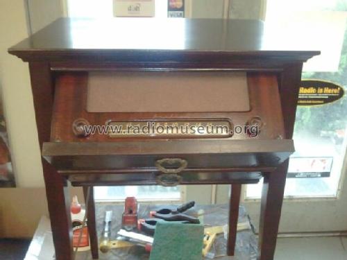
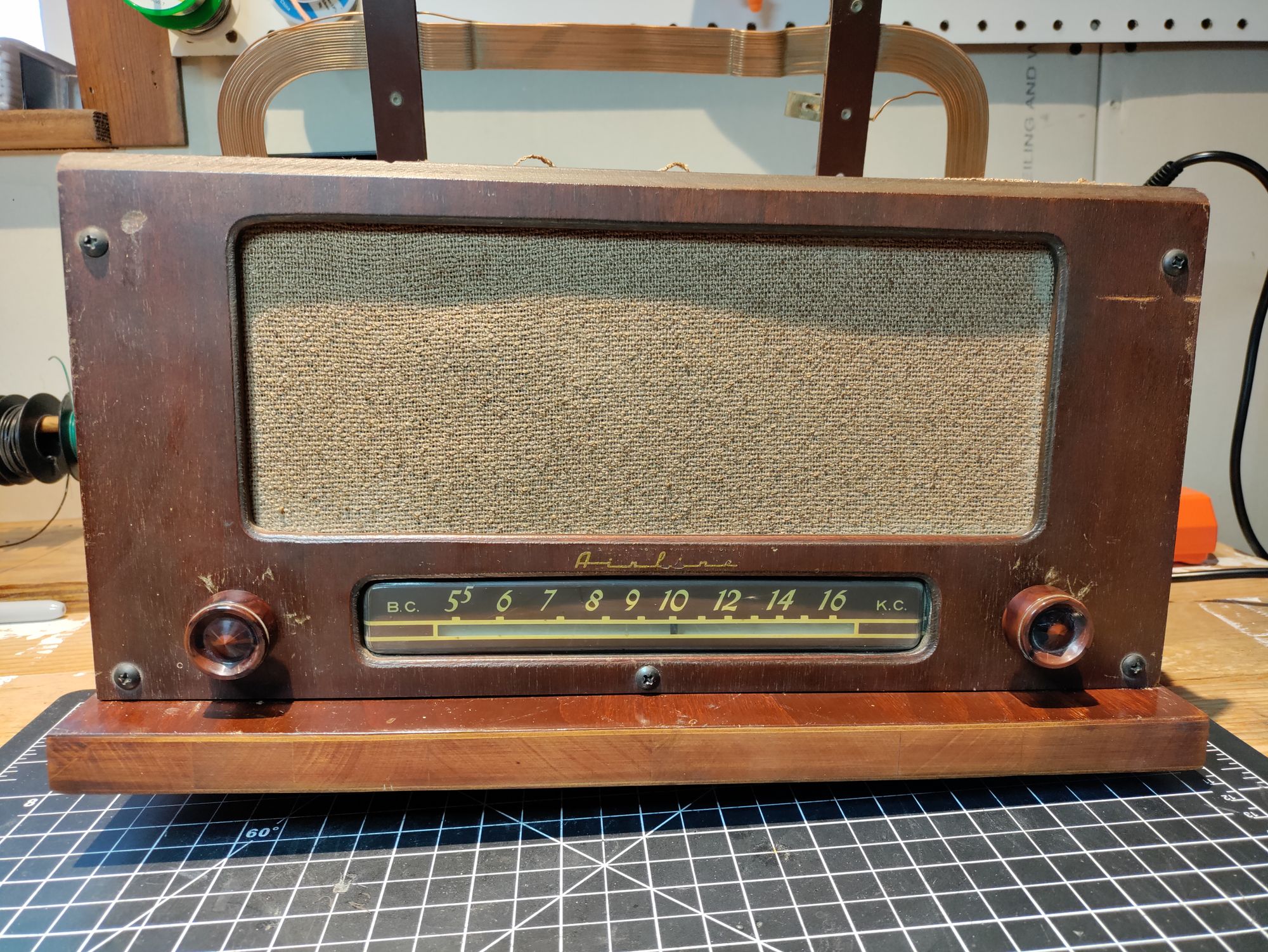
To the unsuspecting eye, the 84KR-2510A looks like any other wooden end table. It has two drawer pulls, but if you try to open those drawers, you will be surprised to find that instead of a drawer sliding out, a panel will pivot out, revealing a radio. A mercury switch inside the radio automatically switches it on when the radio is folded out, so there is no other power switch. Just a volume knob, tuning knob, frequency dial indicator, and the speaker grille cloth.
About
Airline was the brand of radios sold by the Montgomery Ward department store chain. They were made by a few different brands but labeled under the Airline brand. The 84KR-2510A was first introduced in 1948. It is a 5 tube superheterodyne receiver with an IF frequency of 455 kc.
Restoration
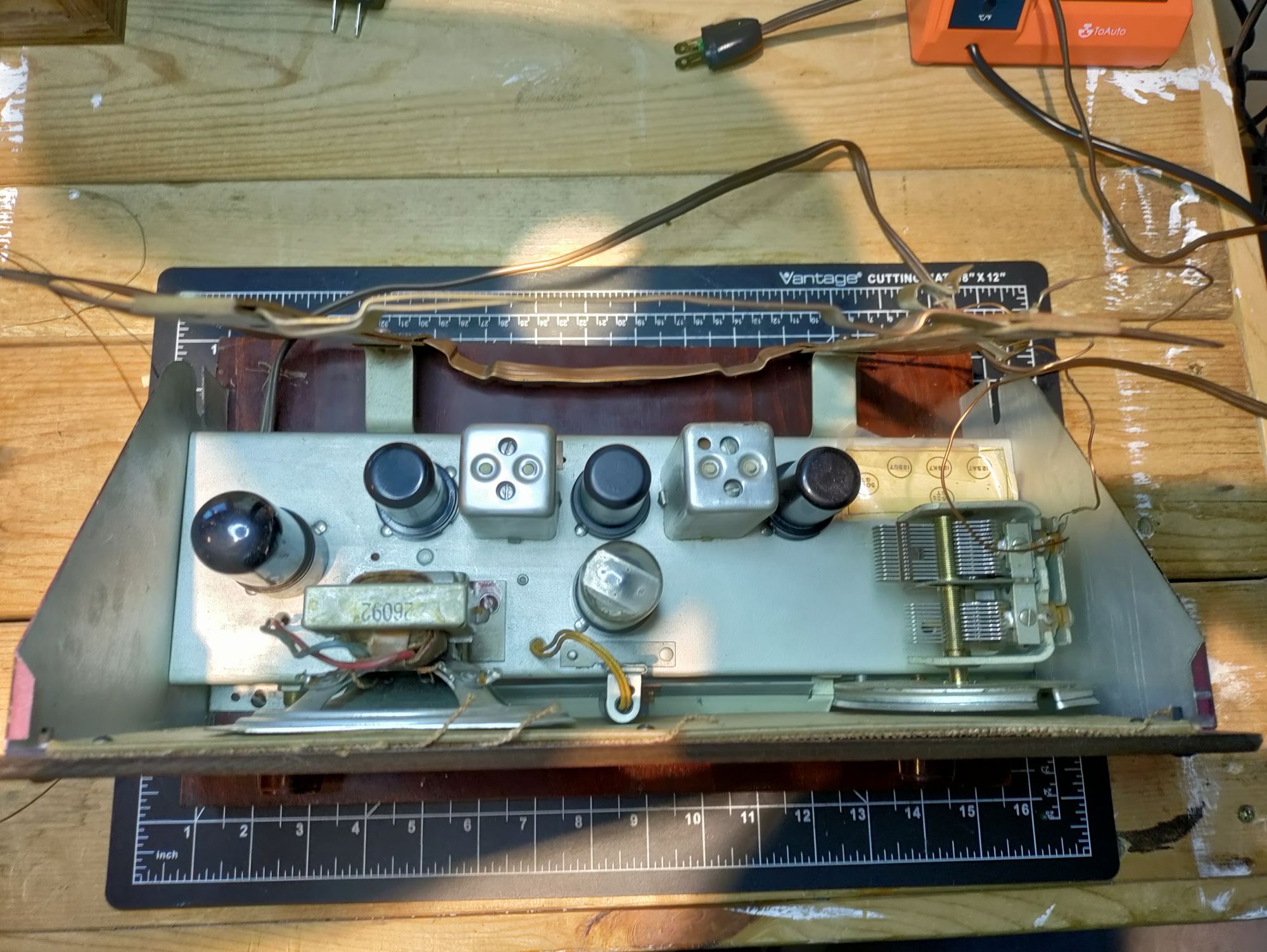
This radio was not a terribly difficult restoration. Upon checking each of the tubes in my Superior TV-10 tube tester, I found that all of them appeared to be good, with the exception of the 12SK7 IF amplifier tube. It initially tested rather weak, but when I tapped the top of the metal can with my finger, the meter needle dropped to nothing. I wasn't sure if this was a fault of the tube or my tester restoration, since I had just recently finished that, so I set the tube aside for the time being. Additionally, the 35Z5GT rectifier tube had a small crack in the plastic base. The glass envelope was intact however, and the tube tested good, so I decided to keep it.
I don't think the radio had been worked on a lot in the past, except for two of the film capacitors which appeared to have been replaced at some point in its life with newer models. Many, if not all of the tubes had been replaced at one point or another, as it had a hodge-podge of different brands in it.
Capacitors
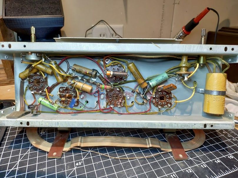
The main job for this receiver was re-capping it. For filtering, instead of the common multi-section filter capacitor in a metal can on top of the chassis, this model had its filtering in the form of a multi-section cardboard and wax capacitor, held to the underside of the chassis with a strap. The three sections of this filter were replaced with suitable Rubycon electrolytic capacitors. Since there was no metal can on top of the chassis like usual, I didn't even save the old filter assembly since it wouldn't be visible on the chassis anyway.
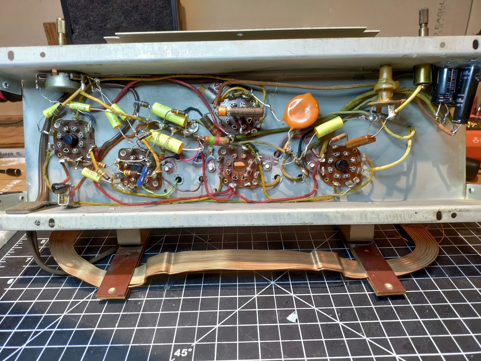
Next up were all the paper and wax film capacitors. There were a decent number of these, and I didn't even bother to check them at this age. I ordered replacements before even getting the radio onto the bench. All of these were replaced without incident, except for a .0005 ufd one, which I neglected to order for some reason, and I had to wait until I placed another order to replace it. All of the film capacitors were replaced with modern yellow tubular ones from Cornell Dubilier, except the .0005 ufd one mentioned above, which was replaced by a Vishay model.
Tubes
After re-capping the radio (except the one foil cap mentioned earlier), I decided to try powering it on and see if it would need more components or if we were at least close. I put all the tubes back into their sockets, and plugged the radio into my variac/isolation transformer/dim bulb power supply. I brought the voltage up slowly in steps, letting it warm up for a few minutes in between, and all seemed well. The tubes all warmed up, the dial light came on, and the dim bulb tester glowed very dimly indicating low current draw. But no sound seemed to come from the speaker, even when adjusting the volume.
Upon closer inspection, I could hear a very low hum from the speaker that did vary with the volume adjustment, but did not change at all by moving the tuning capacitor. I powered the radio down and, remembering the 12SK7 IF amplifier tube that appeared to have malfunctioned on the tester, I pulled it from its socket. I dug through my stash of tubes and luckily found another 12SK7. This one tested good on the tester, and I put it into the socket and powered the radio back up.
After a few moments to warm up, I began to hear much louder static from the speaker, and upon adjusting the tuning capacitor, I heard many AM stations coming in strongly! So, just the one bad tube, it seems. And fortunately, a rather common one that I happened to have on hand and didn't have to order!
Resistors
I went through and checked all of the resistors under the chassis and compared them against the parts list from the Rider's documentation, and found that only one of them actually looked to be out of spec. Suprisingly, it was one of the Allen-Bradley style resistors, rather than one of the "roundy" types, but regardless I went ahead and replaced it. All the others were very close to their specified values and within tolerance so in an effort to keep things as "original" as possible, I left them in place. This radio lives in a climate-controlled basement so the resistors likely won't drift down the road.
Alignment
The alignment procedure was quite simple. As I did not yet have a vintage signal generator in my antique lab at this point, I used my TinySA pocket Spectrum Analyzer. This is a pretty handy bit of kit, and while it's functionality and accuracy are limited, it's hard to beat for the $50 price tag. The TinySA also has a signal generator output functionality, so attaching a short telescoping antenna to it is sufficient for use when aligning radios, although not ideal. It puts out enough signal that when placed close to the receiver antenna, it couples well enough without over-driving the receiver.
For a visual indicator in aligning, I used a 1980's era Micronta FET multimeter for its high input impedance and large analog dial. Using clip leads, I hooked it in parallel with the speaker on the output side of the audio output transformer.
Before aligning the RF sections of the receiver, I re-installed the dial pointer. The old dial cord was broken, so I replaced it using black braided fishing line which works very well! I aligned the dial pointer and verified that its tracking was acceptable across the broadcast band.
Following the documented alignment procedure in the Rider's documentation, I peaked the two IF transformers using plastic alignment tools to avoid pulling the frequency or shorting anything unintentionally. Next, I peaked the tuning capacitor, and by the end of the process, had gotten a decent amount of extra drive out of the receiver and was able to pick up some weaker stations than before!
Wrap-Up
With the alignment out of the way, I did some final cleanup all over the receiver and re-installed the chassis onto the wooden base, placed the front panel back into place, and re-installed the dial knobs and verified everything still worked.
I powered the radio up directly off the AC line power now, without the variac/isolation transformer/dim bulb power supply in place. I tuned around and let the radio really warm up and play for several hours while I worked on cleaning up the bench and a few other tasks around the shack. When all seemed well after a few hours of runtime, I folded up the line cord and prepared the receiver to return to its home.
This radio was a blast to work on, and was very unique! I look forward to seeing it back in its home at my wife's step-grandfather's house in the future, and perhaps even listening to it!
Comments powered by Talkyard.