
This is an ongoing restoration log. Check back occasionally for updates! The full album of photos for this project can be viewed here.
When I started getting into working on vintage radios and collecting vintage test equipment, I knew quickly that something I wanted very badly was a tube tester. This was partly for practicality of course, so that I can test the tubes removed from equipment I am working on, but also just because I think old tube testers are so neat looking.
I started browsing eBay here and there and keeping an eye out for one to pop up that looked right. I had a few false starts when I saw ones that looked good but after doing a bit of research, found that they wouldn't have been what I wanted.
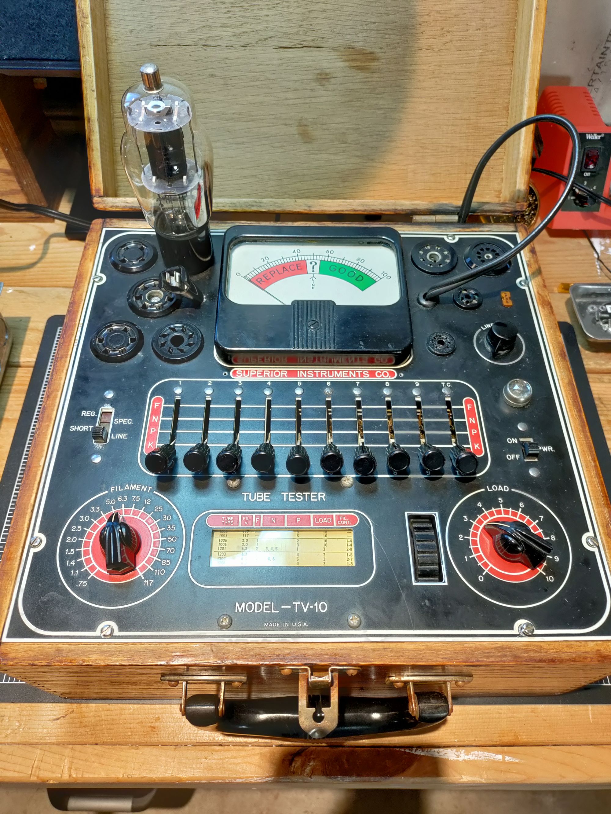
Eventually, I spotted a listing for this Superior Instruments TV-10 tester. Doing my usual research online about the item before buying, I wasn't able to find a ton of information about it, but I did find the manual and tube supplement for the TV-11 which came out a bit later. From what I can tell, this is a very similar model, except that it used a different rectifier, and it included some extra circuitry for also testing condensers (capacitors) and also had a phones jack for testing tubes for noise.
The TV-10 is an emissions-type tester from about 1949. When new, it retailed for about $40, which in 2021 would equate to around $465! Funny enough, I paid only about $50 for the unit when I acquired it. More information about it can be found at the Radiomuseum page dedicated to this unit.
First Look
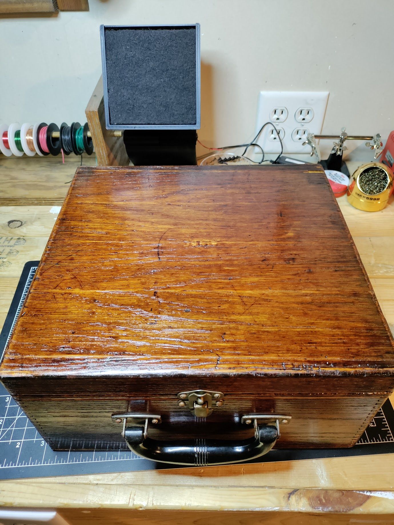
I decided to go for it, from the pictures it looked to be in decent shape. It was of course "as-is" but the fixing is half the fun! When it arrived, I quickly opened it up and got the unit on my bench. The wooden cabinet was in OK shape, but the wood was very dried out and showed many years of use (burns, scratches, scuffs and other cosmetic damage). The hardware was rusty but otherwise decent. The handle had a chunk missing, but not enough to compromise its use.
Inside the unit, it was dusty, but the main thing I noticed was that all the metal surfaces had a thick yellowish crust on them. The tube sockets, lever switches, and even the exposed metal edges where the slide switches protruded. The roller chart didn't quite operate right, it did move freely, but seemed to not have any tension on the paper so it got stuck easily. The meter looked good, but the glass on the face of it had fallen in.
Under the panel, I found a few loose bits of hardware that I held onto until I could find what they belonged to. More yellowish corrosion was found here, and the cloth wiring was very dusty. The autotransformer looked to be in good shape. There were a few carbon composition resistors that would need tested, and a wax capacitor which would also need to be replaced. The capacitor was Micamold branded, which threw me for a second, but as near as I can tell, it was not actually a mica capacitor.
Restoration
Panel Meter
I started with the easy fixes. I removed the panel meter, and opened it up. I cleaned up the glass and wiped the dust out of all the interior surfaces. The glass was held in with several little metal tabs that were screwed down on one end, and extended out over the glass, a bit like the back of a picture frame. I could see that the reason the glass had fallen into the meter appeared to be that it had been impacted at some point, and one of these tabs had bent out of the way allowing it to drop. I simply bent the tabs back into shape and screwed them back down and the glass and meter were as good as new!
Tube Sockets
Next up, one of the tube sockets was damaged. All of its pin contacts were flopping loosely in the socket so that if a tube was actually inserted, they all just pushed out the back. I couldn't figure out how they were supposed to be held in place for a while, but finally realized that the bits of loose hardware I had removed from the box were part of it. A little plastic washer pressed into the back of the socket and held the backs of all the contacts in their places, and then a metal ring/tube bit held that washer in place by press fitting. A drop of super-glue to hold it from coming apart again, and the socket was as good as new! Almost.
Corrosion
I turned next to the corrosion. I knew that old equipment had often used cadmium to plate the steel chassis for rust prevention, so I didn't particularly want to go breathing the dust in. That said, some discussion I had over on the Antique Radio Forums revealed that it was probably not cadmium, at least on the tube sockets. It seems that cadmium wasn't usually used on electrical contacts except certain cases, because it was pricy so it likely wouldn't have been on tube sockets. That said, I still didn't want to breathe it so caution was used to try to minimize getting the dust in the air.
I used a mask and lots of rubbing alcohol to try to keep the dust wet and contained while cleaning. I used a variety of small picks, pipe-cleaners, and tiny brushes and files to try to clean the worst of the corrosion from the tube sockets. They certainly aren't shiny now, but they also aren't brilliant yellow. As tubes are inserted and removed from them, they will be cleaned further. The corrosion was also on many other surfaces including all the lever switches. This was mostly cleaned off with lots of rubbing alcohol and q-tips.
Roller Chart
The roller chart is one of my favorite things about these old testers. It lists basically every common tube at the time of the testers manufacture, and has columns showing the correct settings for the lever switches in order to test them. Many of the testers on eBay were missing the roller chart, or it was in very bad shape. This one had appeared intact in pictures, and indeed, it seemed decent in person. It did roll, but there didn't seem to be any tension on the paper so it bound up easily.
I took the roller chart assembly out of the rest of the unit to examine it. The plastic window over it was yellowed, but otherwise cleaned up nicely. The gears of the roller chart assembly were gunked up so I cleaned them a bit. Since the tester was from about 1949, I had expected the paper of the chart to be in very bad shape and fall apart, but actually it feels almost like new! It turns out the only problem with it was that the 70+ year old scotch tape had disintegrated so nothing was holding the ends of the paper to the wooden spools. I carefully taped it back on, being sure to get it straight as possible so the chart would not bind on the edges of the spools.
Putting it back together was a bit tricky, getting the gears to mesh and keep tension on the chart so that it would operate, but not too much tension either. In the end, I got it done, and reinstalled it and the plastic window into the rest of the unit and it operates quite nicely now.
Enclosure
The wooden cabinet was the next project. Some of the other repairs were done while the cabinet was being worked on, as it was the most time consuming part of the project. The wood was very old and dry, but according to the old advertisements, was oak. The cosmetic damage from the years of use added character, but I did still want to restore it. I started by removing all of the hardware and putting them into vinegar to help loosen the rust. After this, a wire brush helped remove the remaining oxides and leave them looking suitably old and patinaed, but not outright rusty.
I lightly sanded over the entire exterior of the wooden box, which was now in two pieces, lid and main body after removing the hinges. Over the next several days, I applied 3-4 coats of boiled linseed oil to the wood, until it finally stopped absorbing. The wood was VERY dry and drank the oil right up and drew it deep into the grain which did wonders for the dry brittle appearance.
While working on the box, I noticed that the bottom panel was loose, and so using a putty knife, I carefully pried it the rest of the way loose. It had just been glued on originally but the old glue had failed. Using some new wood glue, I carefully reattached it before proceeding further.
After another light sanding, I put a final coat of varnish over the entire outside of the enclosure for additional protection. The boiled linseed oil had darkened the wood significantly and the varnish gave it a nice shine. The burns and scrapes and other blemishes can still be seen with the new finish, which I like since they give it character, but now the box is able to properly protect the instrument inside.
Circuitry
The circuitry in this tube tester is really quite basic, so there isn't a lot to be restored on it. There was one wax capacitor which can be safely assumed to be electrically leaky after 70+ years, so it was replaced with a suitable modern foil capacitor from Cornell Dubilier.
There are a few resistors in the circuit that still need to be checked as there is a good chance they might have drifted over the years, but I have not gotten around to this yet.
Testing
This is a pretty easy apparatus to use once you get the process down. I opted to plug it into my usual safety power supply setup (variac/isolation transformer/dim bulb) so that I can monitor it and adjust voltages. Also, the isolation transformer is nice because in this unit, it used an autotransformer which is tied directly to the metal panel so some care must be taken not to be grounded while touching it, unless isolated.
The first step is to turn on the power switch and make sure the Mode selector is set to Line. The panel meter will come to life, and the idea here is to make sure your line voltage is adjusted properly for accurate test results. The needle needs to be pointing straight up, right in the middle of the "?" section. This model has a rheostat for adjusting the line voltage, and the advertisements claim that it can accept input voltage anywhere from 105 to 130 VAC. I found that the modern 120 VAC requires turning the rheostat all the way down in order to get the needle close to the proper position, so things may not be quite ideal after so many years. However, using my variac supply it is simple to get the perfect voltage dialed in.
Once the line voltage has been trimmed, you can use the roller chart to find your tube you want to test. The chart is quite comprehensive and includes basically every major tube in the industry as of when this device was manufactured, but of course newer tubes won't be on it. I did track down a copy of the supplemental tube list for the TV-11 however, which lists some newer tubes. There are also methods online for how to determine the right settings for a tube which is not on the charts.
Filament/Shorts Test
Once you have found your desired tube, make sure you double check that you are reading the right line before putting in any settings. The print is quite small.
- Start by setting the filament voltage as listed in the chart, and turn the Load knob all the way past 10.
- Next, refer to the chart again and set the lever in the "F" column, and if applicable, in the "N" column. Don't set the lever in the "P" column just yet. All other levers should remain in the "K" position.
- Now you can carefully insert your tube into the proper socket, and if applicable, attach the top contact. Move the Mode switch to the "Short" position.
- The panel meter won't be active for this test. You may need to adjust the line voltage again to compensate for the filament load. One at a time, move each of the levers that are still in the "K" position up to the "P" position and observe the pilot lamp. If it glows, it indicates a short. The only time this should happen is when the numbers listed in the "Fil. Cont." column are tested, which indicates filament continuity. Any other shorts likely indicate a faulty tube. Be sure to return each lever back to the "K" position before moving to the next.
Emissions Test
Now that the filament and pins have been checked and do not have shorts (don't proceed if they do) the emissions test can be performed to determine the strength of the tube. This isn't a very exact test, and a tube that reads in the "Replace" area of the meter may still be functional, it just depends on the way the circuit was engineered.
- Place the Mode switch back to the "Line" position. The remaining steps assume you are continuing from the prior test and the lever switches are still set as before.
- Consulting the roller chart again, place the lever in the "P" column accordingly. The other levers should already be set from the previous test.
- Set the Load knob to the level indicated on the roller chart.
- Move the Mode switch all the way up to the "Reg." position unless the chart specifies using the "Spec." position.
- The panel meter should come to life, and the readings on it should be self-explanatory. That said, as mentioned above, this is a somewhat inexact test, so the tube may still be usable even if it shows "Replace".
Comments powered by Talkyard.