
I love old technology. Ever since I was a kid, I liked opening up gadgets to see the electronics inside, even when I had no idea what any of it actually did. My favorites were always older gadgets though, with the larger, through-hole components where you could really see all the individual resistors, capacitors, transistors, and everything else. Newer electronics are great too, but with so much surface-mounted componentry, it's just not the same.
As I got into learning some electronics for fun when I was in high school, I learned a bit of what some of that stuff did. Then, I started to move my interests toward computers, and I fell in love with vintage computers. My first computer that was truly "mine" was an ancient 286 laptop. The thing was a brick. It originally powered an equally ancient video wall. The wall was being torn apart and thrown out, and I saved the laptop. That laptop helped me learn DOS, and later got me started programming. I later started playing with other vintage computers that my uncle owned, including a Commodore 64, and an Apple IIGS.
When I got into radios a few years back, it was no different. Sure, my main HF rig is fairly modern, an ICOM IC-7100, but like always, I was fascinated by the older, vintage rigs. I think it has to do with that I love to see the progression of technology. Where it has been, and how it got to where it is now. I nearly bought a Kenwood TS-140S rig. I kinda wish now that I had, because it was a killer deal, but I just didn't have the cash at the time.
But where is all this headed? Well, I was recently given two non-working vintage mobile VHF radios by my neighbor and fellow ham, Chris (KEØHGE). He bought them from the estate of a ham who is now a silent key. They weren't in working condition, and he didn't have need of two more VHF radios, but he knew I was hoping to score a couple more to put around the place. So, he gave them to me if I could fix them. It turned out to be a fun little challenge, and my first foray into opening up and repairing radio equipment, so I thought I'd do a little write-up on it.
Patients
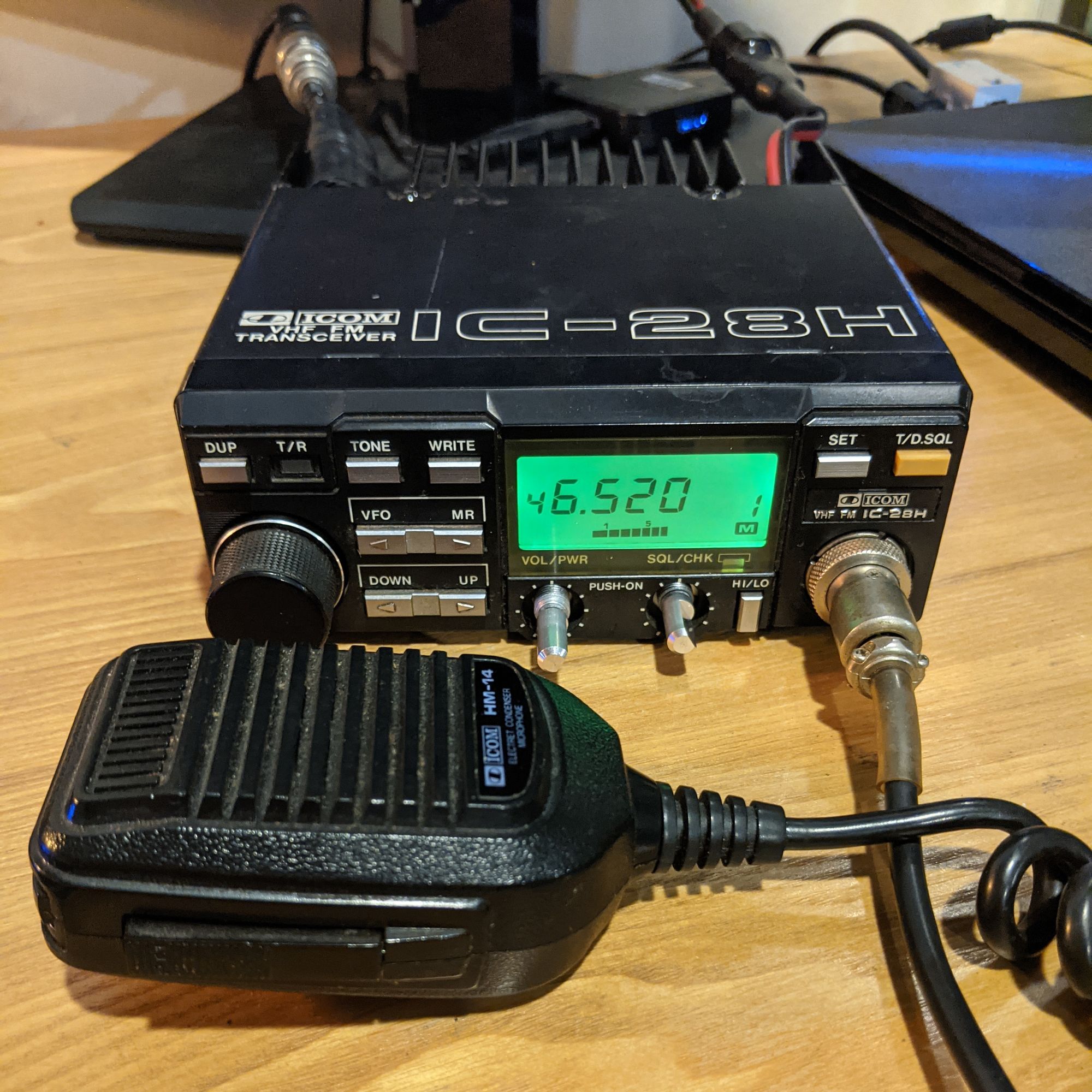
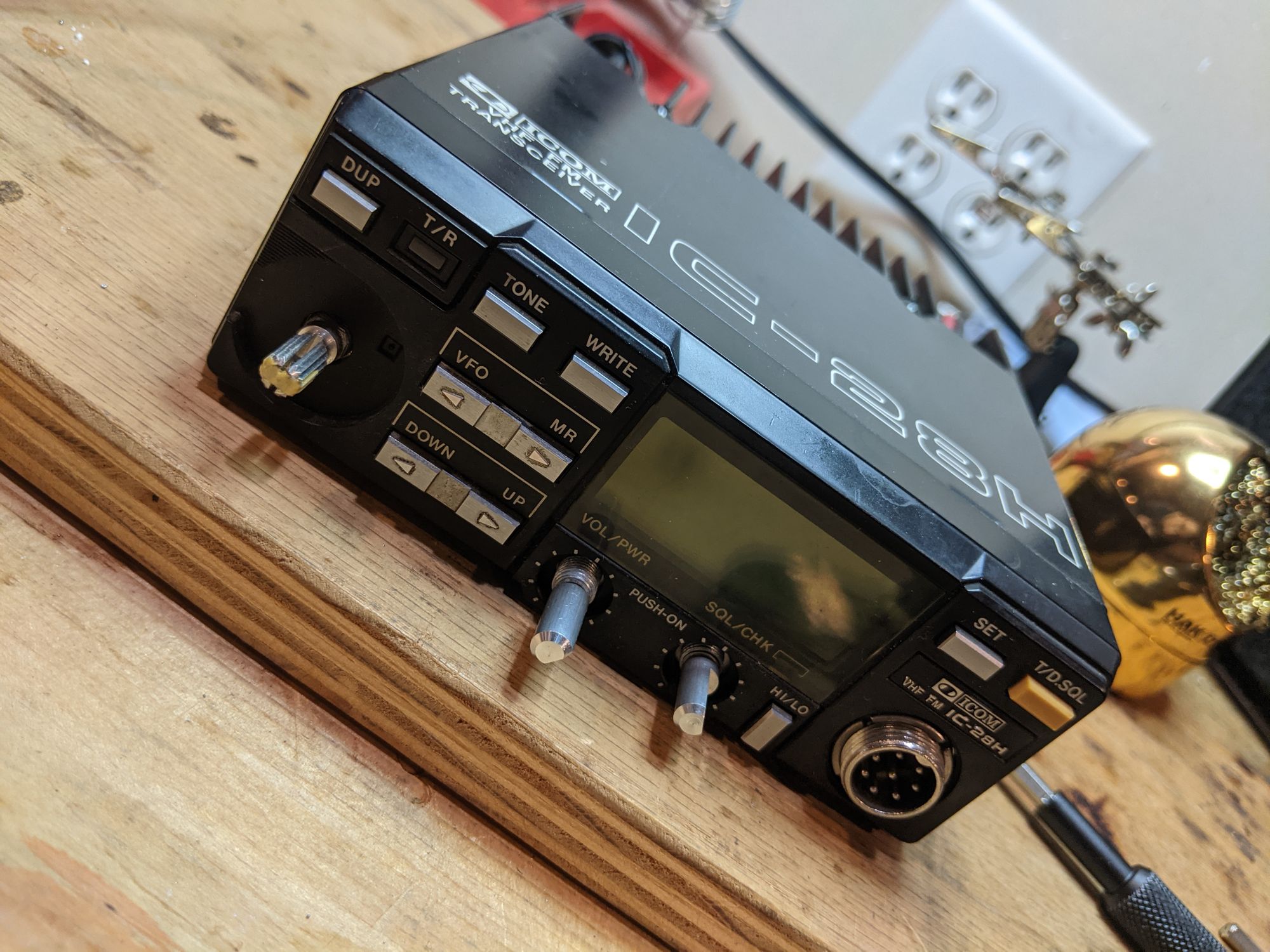
Our patients today are two ICOM IC-28H radios. These are mobile, VHF only, rigs originally came out in the mid '80's and seemed to have been fairly popular, and I can see why. They are a tank of a unit. Capable of 50 watts, and complete with tone and channel up/down capable handmikes, I couldn't believe my luck, getting them for free, even non-working.
They were given to me, along with their original manuals, and some notes made by the ham who had originally owned them, explaining that one needed the volume potentiometer cleaned, and the other needed the squelch pot cleaned. I don't know how long ago these notes were made, but sadly, it seems that he never got around to it, so I am glad that I was able to restore them to working condition, rather than letting them be tossed into the trash. Side note: I found the original receipt from when the original owner bought one of them back in '87 for $420!
Diagnosis
Upon first powering them up, I found that the notes were correct. On one of the radios, the volume control did absolutely nothing. It was stuck at seemingly minimum volume. The other, the squelch was stuck at wide open, or very close to it. Should be an easy score I thought, and I went to the hardware store and picked up a can of CRC electrical contact cleaner.
Unfortunately, the problem seemed to be deeper than a good spray-down with contact cleaner could get. I'm guessing the wipers were dried out or something was perhaps shorted, since turning the pots had no effect at all. It seemed that it was going to be time to find replacement pots to put in, if I was going to do this job right.
Finding Organ Transplants
I started by doing some research about this model of radio, and found that it seems the potentiometers are a common failure point. Knowing this, I was able to, with some help from another local ham, John (NØWJS), find a few forum articles where other people talked about replacing the pots in IC-28 radios.
I was able to track down an original service manual for the radio, with a parts list, and found the model numbers for the original parts. A user on one of the forums I was reading suggested that they looked like Alpine part numbers, although they were no longer available. From here, I was able to go to Alpine's website and browse through their entire catalog, and narrow it down to a couple of modern pots that seemed to be comparable, with a few minor differences.
For the volume/power, the service manual lists a RK0941114 (10KB), and for the squelch it has RK9A12 (10KA). As one of the forums pointed out however, I think these maybe swapped, as it seems the audio taper should be on the volume, and the linear taper on the squelch.
From Alpine's website, I decided to get the RK097111202P, and for the squelch I chose the RK0971214Z06. Even though I technically only needed one of each since the other of each still worked, I decided to order two of each while I was at it and paying shipping. These components are clearly a weak point, so I figured the others would fail sooner than later anyway, may as well replace them all while I'm at it.
Cutting In
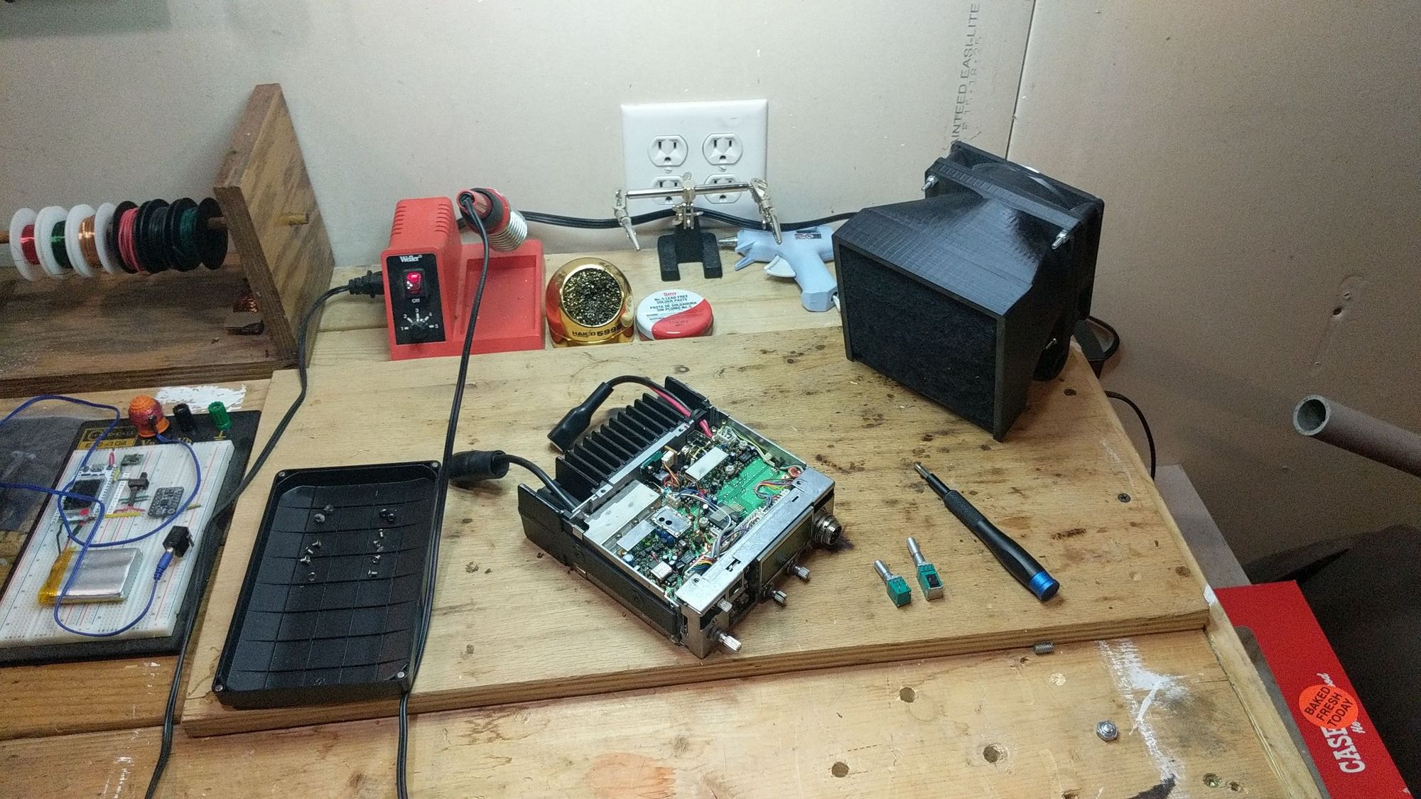
Opening up the IC-28H is delightfully easy. This, combined with the availability of a service manual, with complete BOM and schematics demonstrates that this radio was designed to be repaired, not just thrown out like so many consumer electronics these days.
There are two Philips screws each holding the top and bottom panels on. I used care when removing the bottom panel, as it has a speaker mounted to it which has a header that must be unplugged from the board. With those removed, this exposed two more each of Philips screws on the top and bottom of the unit, holding the front plastic bezel on. I also pulled the volume, squelch, and tuner knobs off at this point. I think they were glued at one point, but the old glue didn't put up any fight.
This allowed the front bezel to be removed easily, exposing the odd nuts holding the pots to the front panel. The nuts are round, with a slot in them, rather than the usual hex shape. I was able to loosen them with a little care though, and the pots were free.
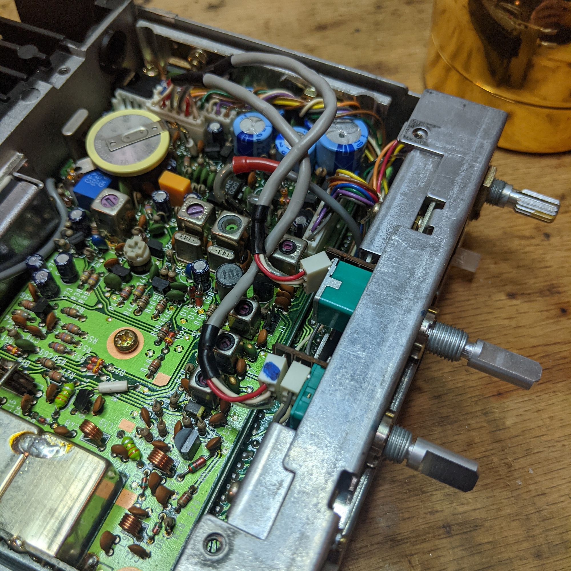
At this point, it became necessary to remove two final Philips screws each on the left and right sides of the unit, freeing the front panel from the main body, and leaving it attached only by several wiring harnesses, and allowing the old potentiometers to slide out freely to dangle from their wiring harnesses.
In order to give myself more room to work, I went ahead and unplugged the six pin header from the board where the two harnesses plug in, as well as unplugged the little two pin header from the other side of the unit where the power switch connects. This left the two knobs and their wires attached only by the two wires from the squelch that are for the momentary Tx monitor switch. These were not easily removeable from the board without cutting, so I left them be. There was already enough slack for me to be able to maneuver enough to get the job done.
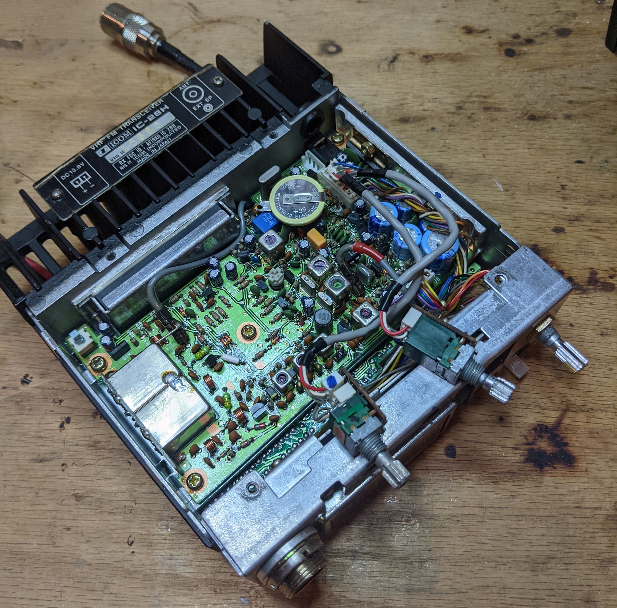
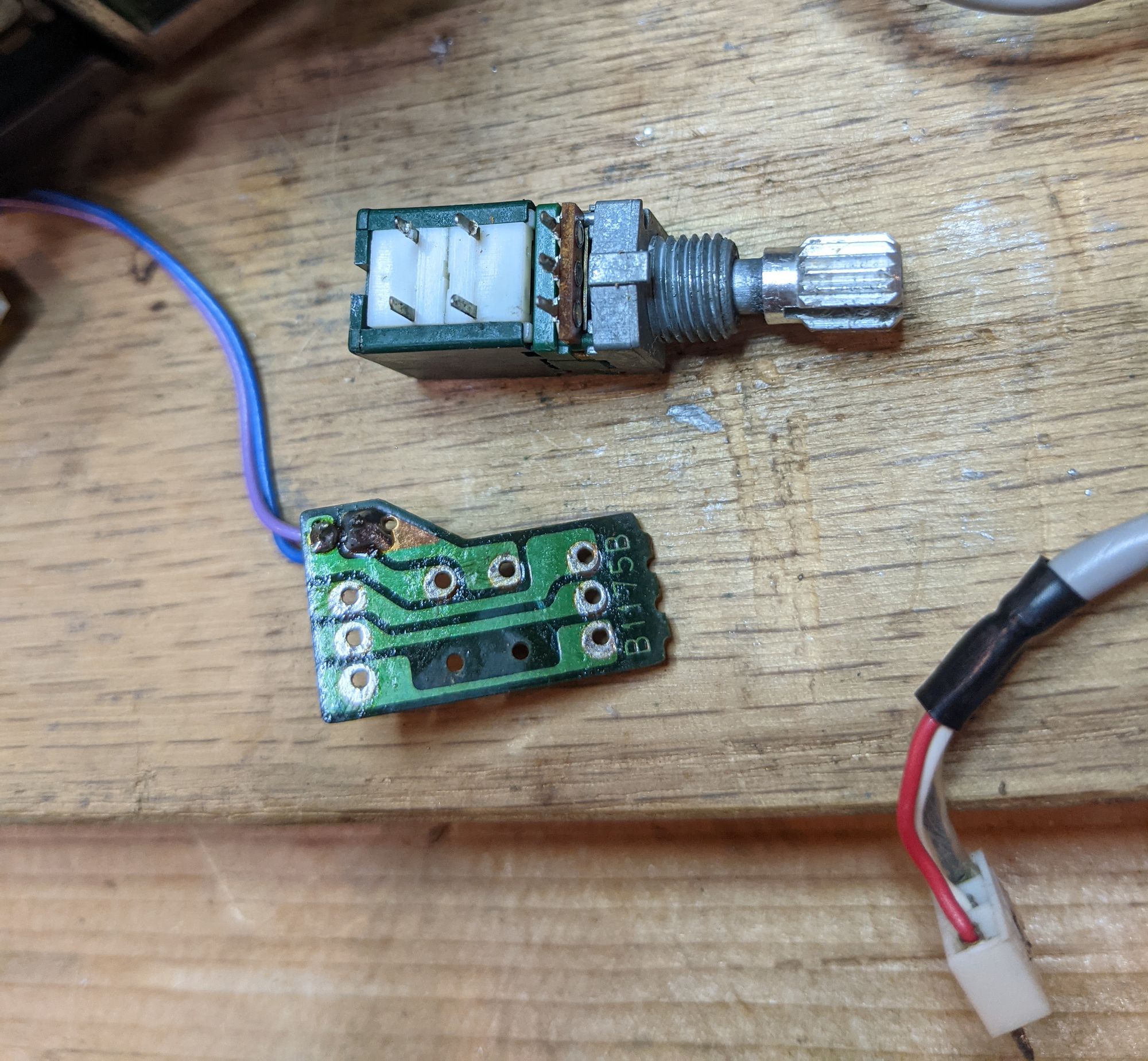
Each of the pots connects to its wiring harness by being soldered to a small PCB, and the wires connect to the back of this board through soldered headers. I had hoped that the new pots would share the same footprint as the old ones and fit these boards, but I was prepared to just cut and solder the wires directly if not. Now was the moment of truth.
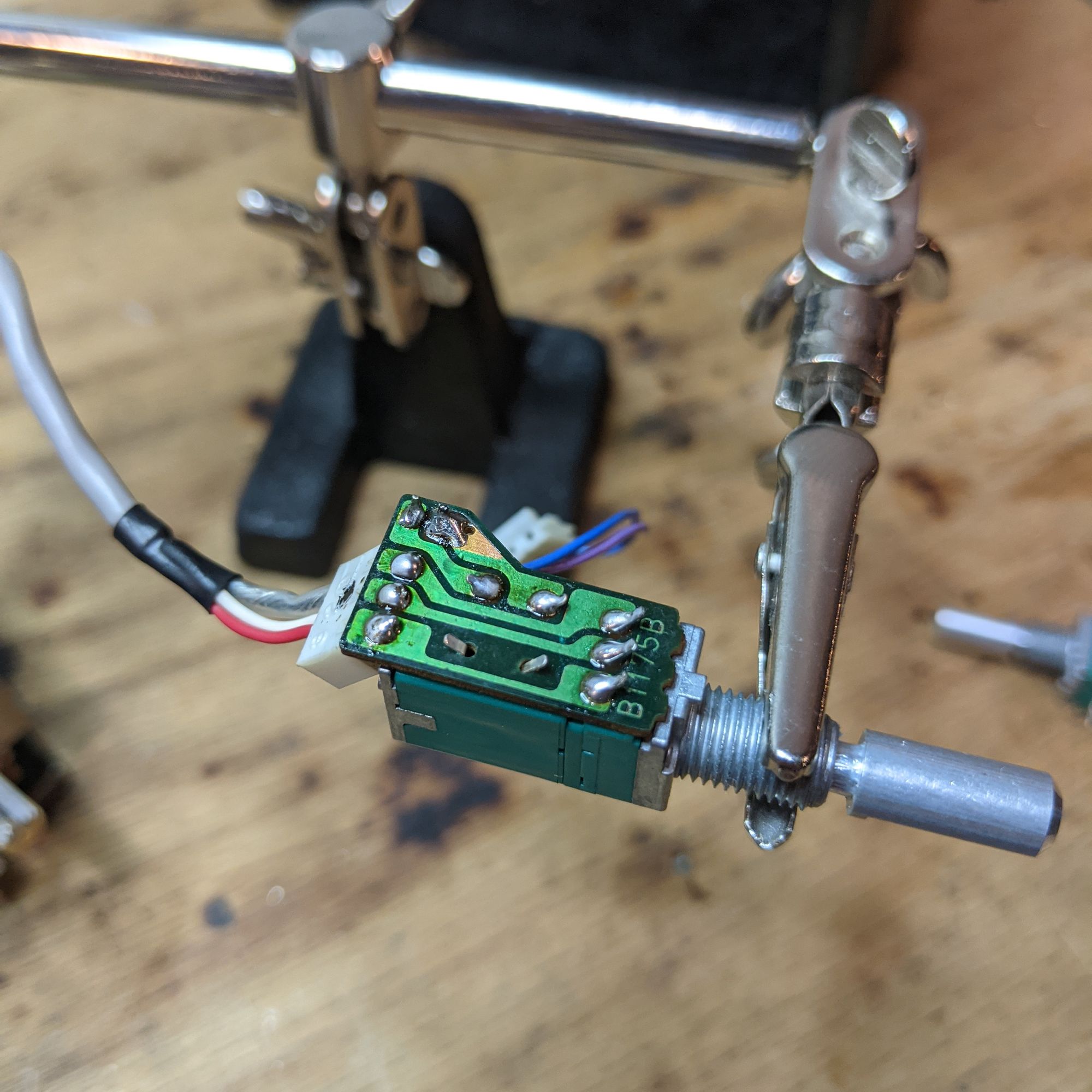
As it turns out, they ALMOST fit. Each needed just a bit of modification to work. The volume/power one was the trickier of the two. After using some copper wick to desolder the old pot and clean the pads, I was able to hold the new one up to the board. The new pot is a decent bit longer in body than the old one, so it was going to clash with the wiring header on the back of the board. I went ahead and desoldered this as well, and cleaned the pads. The two pins on the side for the power switch could stay where they were.
The next problem is that the three pins for the pot itself, and the two sets of pins for the on/off switch (it's technically a DPST although we only need SPST) are slightly further apart than the original. I was able to coax it into working however, by gently bending the pot pins inward a bit, and the two sets of switch pins inward a bit, until they lined up with the holes on the PCB. From here, I was able to slowly guide the board down onto the pins, bending them further into position. I then bent the tails coming through the board back the other way to help hold the board tightly in place, and resoldered everything. It's not ideal, but it's more than adequate.
As for the wiring header, it now couldn't reach its original holes with the back of the pot partially blocking them. However, I was able to bend the three header pins just a tiny bit and then work them into their holes just far enough to solder them. I was careful to make sure they weren't under tension before soldering, so that the solder isn't under stress.
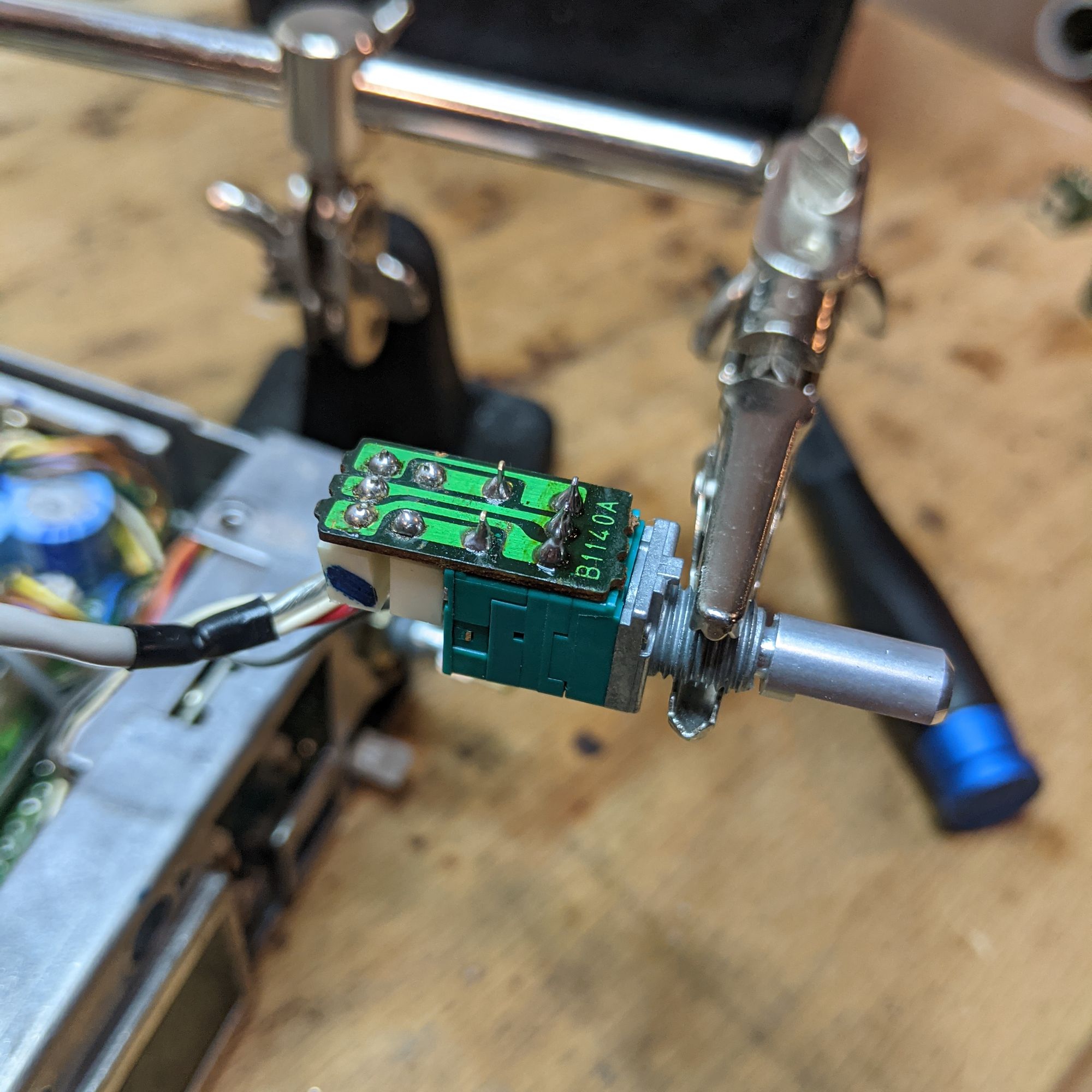
The squelch knob was much easier. I started by doing the same as with the volume pot, and desoldered the old one off the board using copper wick, and cleaned the pads carefully. The profile of the new pot is almost identical to the old one, the only problem is that the new one is a 2-gang pot, so that extra set of three pins on the front was going to be a problem. It was easily remedied though, by simply nipping them off carefully, as close to the board as possible.
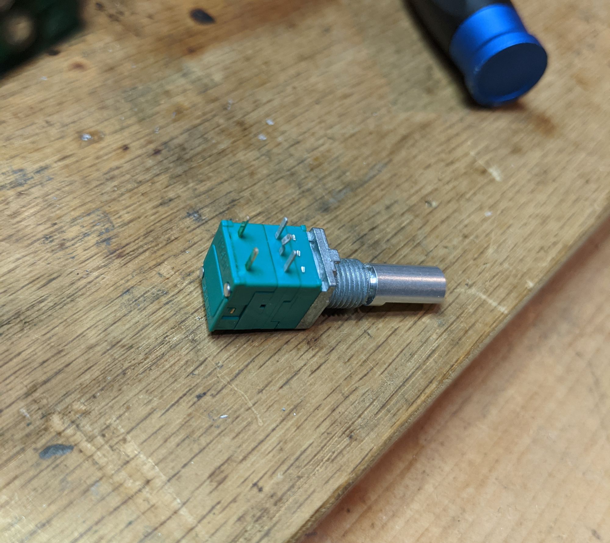
With the extra pins out of the way, the remaining 5 pins fit perfectly into the existing holes, and the wiring headers could stay exactly where they were without clashing with the pot. I soldered all the pins back to the board, and the replacement was complete.
At this point, it was time to test things out and see how badly I'd messed up. I took the radio, guts hanging out, over to my radio bench, and plugged it into a spare set of PowerPoles, waiting for the smoke to come out, but miraculously, it didn't!
I carefully clicked the power switch on, and turned the volume slowly up part-way, then started lowering the squelch, waiting for the static to start. After a bit, the Rx light came on, but I heard nothing. I panicked and started wondering what I may have done wrong. Then I realized I hadn't plugged the speaker back into the board. Whoops. Once I plugged it back in, I nearly blew my ears out because at this point I had the volume turned way up, and the squelch way down! After adjusting this though, everything seemed to be working. I tested the momentary switch on the squelch for the Tx monitor and it worked too. Time to put it back together!
Stitching Up
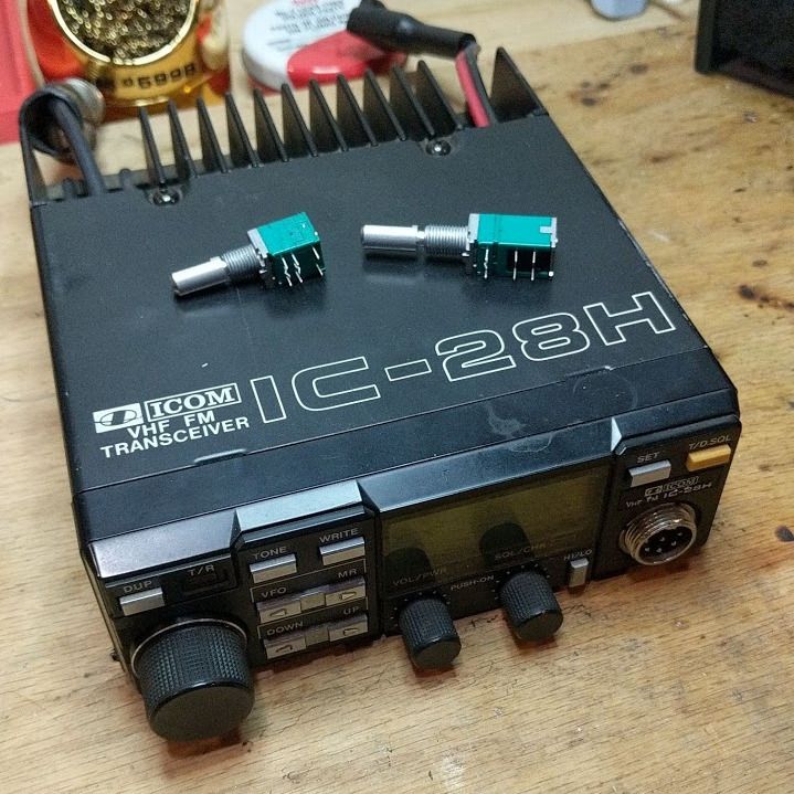
I returned with my jumble of wires and components to the workbench, and carefully remounted the new pots to the panel. Unfortunately, the other difference between these and the originals, is they are longer, both in threads and the shaft itself. Eventually, I may open these back up and try to add some spacers behind the panel to try to even them up, but for now, I don't mind. Additionally, the original knobs won't fit without modification either. They are for a slotted knurled shaft, but the replacements are flatted. Again, a problem I may address in the future, but not right now.
I tightened the nuts back down to secure the pots to the panel, and plugged the six pin header back into the board, and plugged the two power wires back in on the underside. At this point, I would have been wise to test some more, but I got in a hurry and went ahead and put everything back together, front bezel, cover panels, and all. I took it over to the bench again for a test, and this time, when turning it on, the volume was very low. It was adjustable, but went from "nothing" all the way to "very quiet". Something wasn't right. Perhaps a short?
I took it back to the bench and opened everything back up, something a surgeon never wants to have to do after an operation. After some fiddling around, I found that one of the red wires on the six pin header was loose and jiggly, and after a little tinkering, I was able to get it secured, and put everything together again.
This time, all the testing went perfectly. I was able to check into a local 2m net that was beginning just a few minutes after finishing the project, and all worked perfectly!
Wrap-up
This still left the second radio to be repaired, but the process was uneventful on that one. I didn't have time that same evening to repair it, but the next morning I got up early, and went to the shack to work on it. After having found all the potential problems during the repair of the first one, the second went very quickly, and had no major hiccups. It also works perfectly!
As I mentioned, the new shafts are too long, and the original knobs do not fit. This is something I would like to remedy some day, probably with a few spacers on the back of the panel, and maybe cutting down the shaft. The knobs I think could be made to fit by drilling them out just very slightly. They aren't intended for flatted shafts though, so glue would probably be needed to make them work. I may just get different knobs for them.
Overall, this was a very fun and rewarding project! I learned a lot about how my radios work, and got lots of good experience out of it. In the end, for just about $25 in parts and shipping, I got two perfectly working vintage 2m radios out of the deal!
If you have any questions about this project, feel free to contact me, I'll be happy to answer them!
Thanks for reading!
Michael (KEØTCF)
73
Comments powered by Talkyard.